temperature controller manual
1. INTRODUCTION
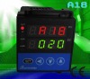
- A18 is an economical and easy to operate industrial temperature controller. It is designed for various applications, for plastic industries, food processing equipment’s, packaging equipment’s, environmental test instrument’s and general In-process temperature controls (e.g. Furnace, Drum heating, Pipe line heating) .
- Using Advance artificial intelligence control algorithm with Auto tuning, A18 reduces the “overshoot” problem without the need of going through a complicated PID parameter setting pre-run. A18 can achieve precise controls with minimum set up time.
- It has an advanced Modular Output structure allow various outputs options be configured for quick delivery. This also allows easy field service and to implement regular maintenance program (example, replace a new Relay Module for every 100,000 hours of estimated switching operations)
- It can be operate with universal line voltage, of 100~240VAC 50/60 Hz power supply.
2. Specification's for temperature controller:
- Range: K (0-1300C), S (0-1700C), R (0-1650C), E (0-800C), J (0-1000C), PT100 (-200-600C), Customize voltage and Current.
- Accuracy: 0.3%± 1 digit (LSB).
- Measuring Resolution: 0.1C/ 1 C.
- Power: Universal 85-264Vac 45-65Hz.
- Power Consumption: < 5 W.
- Operating environment: 0-50C, RH <85%
- Control Output Options.
- Relay Contacts: AC220V/5A resistive load.
- DC voltage: ForSSR trigger, >12V. 20mA.
3. Self Tuning Operation:
One of the key features of A18 series is, by performing the Self Tuning; the PID parameters are set by the internal Fuzzy Logic computer. Therefore, user with little experiences in PID set up; can easily operate the A18 series, without any delay or problem.
The fuzzy logic computer is proven in many applications and able to determine the PID with just one Self Tuning process. The controller "learn" during the self tune process, its the characteristic of temperature rise and changes, and adjust the PID parameters automatically to ensure the temperature rise with minimum overshot at reasonable ramp up time
MODEL CODE SELECTION:
| ITEM | CODE | DESCRIPTION |
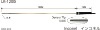
| 1.Size | A18 | Z | 48*48*110mm |
2. Output mode | S | SSR Voltage output :12VDC/20mA (used to drive SSR). |
| R | Relay |
4. FRONT PANEL AND OPERATION
Basal display status:
When power on, the upper display window of the instrument shows the process value (PV), and the lower window shows the set point (SV). This status is called basal display status. When the input signal is out of the measurable range (for example, the thermocouple or RTD circuit is break, or input specification sets wrong), the upper display window will alternately display "orAL" and the high limit or the low limit of PV, and the instrument will automatically stop output.
Parameter Setting Flow Chart:
5. OPERATION DESCRIPTIO
Artificial Intelligence control and auto tuning
When A18 Control method (Refer to 6. Parameter & Setting) is chosen, the Control parameters (PID) can be obtained by running auto-tuning
At the first time of running auto-tuning, during measure/operating statuses, press"<<" for 2 seconds, "At"(Auto Tuning) will flash at lower display window and the instrument execute its auto-tune controls... After several cycles of Controls action, the instrument will obtain the values of PID control parameters. If you want to escape from auto tuning status, press"<<" and hold for about 2 seconds until the "At" flash stops. Depending on the physical temperature control system set up, the time of auto tuning can be several seconds to several hours. Once the auto tuning completed, the parameter "CTRL" automatically set to 3 (the initial value is 1) or 4, no more auto tune is allowed. That is to say, if another "auto tuning" is needed, user will need to enter Field Parameter Table Set up mode again, to set the Control parameter "CTRL" to 2.
Practical Consideration before running an Auto-Tune
Note 1: Before running auto-tuning, set point should be set to an often-used value or if not, set to a middle value before initiate an auto-tuning. Generally, for application with 10%~80% time on heating can obtain satisfying auto-tuning result. If the heating time is not in the range of 10~80%, the auto-tuning will run for a long time and can't get satisfying result. Raising set point for heating time less than 10% or decreasing set point for heating time greater than 80% can improve auto-tuning result.
Note 2: Don't modify the set point during auto-tuning. It may affect the precision of auto-tuning.
Note 3: After auto-tuning finishes, generally, the temperature rising has a little over-shoot (about 1~3°C). It is because considering that the transducer is often placed between the heater and heated material, and a little over-shoot can shorten the time of rising to set point and save Power. (Generally, the temperature of transducer can be raised quickly than that of heated material).
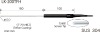
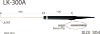
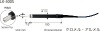
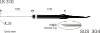
6. Details photo of temperature controller :