please read the instruction manual carefully and all operational links to ensure data accuracy.
1.summarize
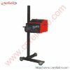
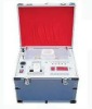
SV-D1T –headlight tester (hereinafter referred to as “tester”), boasts the advantages of accuracy measurement and simple installation, is used to detect the luminous intensity and the illuminating position (or the axis deviation).It is suitable for the auto manufacturer, .vehicle repair unit and environmental- protection department.
1.1 The main technical parameters
1). nominal range of use:Temperature: 0-40°C
Relative humidity: ≤80%
Power: AC220V-DC5V or four R20 batteries
2). Measurement range: Luminous intensity: 0-40000cd 0-80000cd
Axis deviation: vertical direction: UP 1º20´——DOWN 2º20
Horizontal direction: LEFT 2º20´——RIGHT 2º20´
3).Indication error of luminous intensity: ±12%
4).Deviation error from the optical axis: ±15’
5).Measuring range of lamp height: 0.4——1.3m
6). Measuring distance: 1m
7).Weight: 25kg
2.structure:
The tester is composed of light pigeon hole and running gear. The light pigeon hole can move alone the column by shaking hand wheel with the method of drive in gearwheel and a pinion. Its movement in left and right is completed by rolling wheel at bottom.
3.Basic principle
The internal structure of light pigeon hole is shown in figure 3 (A).The tested light will enter into pigeon hole after lens and be reflected to screen by illuminator. Five light testers will be symmetrically showed in the screen as figure 3(B). “NO.1”and “NO.2”is to test the light distribution in vertical direction and its balance output should be connected with axis balance indicator (UP and DOWN). “NO.3”and “NO.4” show the light distribution in horizontal direction and its balanced output should be connected with axis balance indicator (LEFT and RIGHT). “NO.5”shows the luminous intensity of which the output should be connected with luminous intensity indicator. The angle of illuminator could be changed by separately running the axis dial (LEFT, RIGHT or UP, DOWN) to make every axis balance indicator “zeroing”.
4,Installation
4.1 Ground requirement
The ground where tested vehicle park should be flat and its degree of level should be over 4 mm/m(2º45´).
4.2 The tester installation
At first, please separately install three bolts for idler wheel at the two sides of the under pan with which fixed the crunch by three “M10” bolts.
When the hand wheel is fixed with chassis, placing the light pigeon hole at the column by gear engagement(figure 1),press the button in hand wheel while shaking it to move the light pigeon hole up and down ,release the hand wheel when it reaches the predetermined position.The left and right movement could be completed by pulling the left and right handle a1.nd try to keep its stability.
Made observation on the bubble at the top of the light pigeon hole(figure 4) and make sure that its position lies within the center line(figure 4B) .Only modest deviation, whose edge is not exceed center line, is allowed. The adjustment for horizontal position of light pigeon hole is needed if the bubble edge is exceed center line.(figure 4). When adjustment starts, the three tap bolts should be loosened to change its horizontal angulations and make bubble lies within the center line
5.Usage method:
5.1 The requirement for the tested vehicle./
The tested vehicle of which only one people sit allows in the cab should be in no load conditions .The tires should be blow up and batteries should be at full condition. At last, please make sure that the front glass shell is cleaned.
5.2 The testing distance
The position of tested vehicle parks should make the distance between reference center height of headlight and condensing lens of light pigeon hole be 1m.
5.3 The right position for tested vehicle
When test starts, the longitudinal center line of tested vehicle should be paralleled with the optics center line and you can check it by imagine sight at the top of light pigeon hole.
Notice: The place with vehicle guide-line draw could be taken as the reference for the position adjustment.
5.4 The test step
A, turn on the headlamp and move the tester to the front of it to make the light shed on the collecting mirror.
B,Open the lip of image foresight from which you can make observation of the tested headlamp, move the light pigeon hole to make the image of tested headlamp to be at the midpoint of the image foresight(figure 5).
C,Turn on the power and switch it to “400”.Repeatly revolve the knob in the optical axis dial (Left, Right and Up, Down) to make the “optical-axis balance indicator” points at the center position while the luminous intensity of the tested headlamp is shown in the “luminous intensity indicator”. If the indicator exceed the scale range, Switch the power to “800” make the “luminous intensity indicator” point at “80000cd”
D,Repeat the same operations for another headlamp.