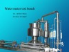
I. General Information
The water meter testing benches FYL-LS-6B – DN40-150 is designed strictly according to the following standard:
GB-T778.1-1996:Specification
GB-T778.2-1996:Install requirement
GB-T778.3-1996:Test methods and test equipment
JJG162-2007:Verification Regulation
The bench is available to use the volume comparison method to test water meters DN40mm, DN50mm, DN80mm, DN100mm and DN150mm.The equipment can supply whole bench characters analysis and errors inspection to a single water meter. To ensure the equipment smoothly operation, Mechanical method only and mechanical combined with cameras are selective ways, the later gives more convenient. Products are offered to the manufacturer of the water meter, repair factory, measure department, large-and-middles-scale industrial and mining enterprises, and railway water and electricity ones. The product is well known by the features of High precision, easily operation and simple maintenance.
II. Main Technical Parameters
- Device accuracy: 0.2
- Device calibration method: the volume comparison.
- Standard graduate cylinder: gourd-style double-necking with 2 gauges, the lower half of one gauge have a volume of 0.1m3 and the whole is 0.5m3; another gauge has the lower half 1m3 and the whole 3m3. The necking part of the standard measure of the corresponding volume of water per liter higher than the national standard height.
4. Instantaneous flow meter: measured precision ≤ level 2.5, is divided into four glass rotor flow meter, one for the shunt orifice flow meter:
4.1 LZB-25,70-700L/h,DN15 ball valve control.
4.2 LZB-50,450-8000L/h,DN25 ball valve control.
4.3 LZB-80,7-35 m3/h,DN50 ball valve control.
4.4 LZB-25,40-180m3/h,DN150 Worm manually control valve , a ball valve DN25 for the flow fine-tuning purposes next to shunt orifice flow meter..
5. Clamp meter devices: pneumatic, telescopic distance: about 240mm.
6. Commutator: piston.
Trip distance: 180mm.
air source pressure: 0.35~0.5MPa.
When pressure of gas source≥ 0.4MPa, the time tolerance of the Commutator movement is less than 0.1% as one shortest flow time go.
7. Water pressure: 0.25~0.4MPa.
Water pressure should be no discernible pulse phenomena, the slow changes in water pressure caused by fluctuations in the instantaneous flow coefficient is not more than 1%.
8. Power: 380V, 50HZ three-phase four-wire.
9. Calibration dimensions of the test bench are nearly: L × b × h is about 7400 × 2800 × 3400mm.
10. Total weight of bench: 3t.
III. The components of the system and the calibrate principles
- Equipment components:
inlet pneumatic valve→clamping system→front straight tube→water meter→back straight tube→flow rate controller→instantaneous flow meter group→Commutator→standard graduate cylinder→outlet valve→control panel.
- Water meter calibrate principle
Choose the flow point and the corresponding straight tube, make the Commutator at drainage position where the outlet valve opens, then open the inlet valve, open the flow control valve, let the water circulate at the standard flow, drive out the air in the meter and tubes, then close the unused flow controller, make the water flow at the fixed flow point, note the initial number of the tested water meter, change the direction of the Commutator, read the cubage number from the rule after the standard graduate cylinder number fixed. Finally compute the error according to the following formula:
While: is the error of the water meter:
is the number of the standard graduate cylinder:
is the number of the water meter.