Phase volt-ampere meter, clamp phase meter, digital clamp phase meter
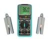
SMG20000E Double Clamp Digital Phase Meter is special designed for voltage, current and phase tests, it is in high-precision, low price, portable hand-held, dual-channel input measuring. It’s easy to measure the phase between U-U, I-I and U-I, identify the inductive circuit ,capacitive circuit and the phase sequence of three-phase voltage, detect the wiring group of transformer, test the secondary circuit and bus differential protection system, display the phase relationship among the CT groups of a differential protection system, and check if the wire of electric meter was correctly connected. When testing customers do not need cut off the tested current which input by clamp-current transformer. When measuring the phase between U1 and U2, the two input circuit loop are completely isolated, so the possible misconnection is absolutely avoided, which may result in short circuit and may even burn the meter. The monitor of the device is high-contrast LCD screen, and the character in big size, which helps to obtain the best visual effects.
Products features
1. ingenious structure, easy to operate.
a. hand held structure
b. you should not disconnect the circuit or change the measurement range under 10mA-10A , 3V-500v.
c. use high contrast LCD, character can be 25mm, the screen angle can be 700, to obtain the best visual effects
d. the function and layout of the switch are reasonable, rotating can read the measuring voltage ,current and phase.
2. high resolution
adopt new type patent current clamp , current resolution up to 0.1mA; voltage resolution up to 0.1V.
3. Low power consumption
this product with micro power consumption design and with the function of testing the voltage of battery.
Products parameters
Intrinsic Error
1. Reference Operating Conditions
(1)Temperature,(23±5)°C
(2)Moisture,(45~75)% RH
(3)Wave forms of measured signal,sine wave,β=0.02
(4)Frequency of measured signal,(50±0.2)Hz
(5)Position of Measured current carrying conductor in the nipper jaw,Optional position
(6)Amplitude range of measured signal when measuring phase
100~220V,0.5A~1.5A
(7)External reference frequency electromagnetic interference should be avoided
2. Limits of Intrinsic Error
(1 )AC Voltage(see Table 1)
Table 1 Error of AC Voltage |
| Measure range | Resolution | Limits of intrinsic error |
| 20V | 0.01V | ±(0.3%RD+0.2% Range) |
| 200V | 0.1V | ±(0.3%RD+0.2% Range) |
| 500V | 1V | ±(0.3%RD+0.2% Range) |
Input Impedance,All the measure range is 2MΩ
Voltage input impedance of phase testing >500KΩ
(2) Alternating current(see Table 2)
Table 2 Error of alternating current |
| Measure range | Resolution | Limits of intrinsic error |
| 200mA | 0.1mA | ±(0.3%RD+0.2) |
| 2A | 1mA |
| 10A | 10mA |
(3) Phase
U-U,U-I,I-I(see Table 3)
Table 3 Error of Power-frequency Phase |
| Range | Resolution | Limits of intrinsic error |
| 0~360° | 1° | ±2° |
Impedance of input voltage loop when measuring phase of U1-U2,40KΩ
Operating error
1.Rated Operating Conditions
(1)Temperature,0°C~40°C
(2)Moisture≤90%
(3)Wave forms of measured signal,sine wave,β=0.05
(4)Frequency of measured signal,(50±0.5)Hz
(5)(5)Position of Measured current carrying conductor in the nipper jaw,Optional position.
(6)Amplitude range of measured signal when measuring phase
Phase U1-U2,30V~500V
Phase I1-I2,10mA~10.00A
Phase U1-I2 or I1-U2,10V~500V,10mA~10.00A
(7)External reference frequency electromagnetic interference, should be avoided
2 . Limits of Rated Operating Error
Under the conditions described in 1, the limits of the rated operating error will not exceed twice of the limits of intrinsic error.
Othertechnical features
1 .Display,three and half
2. Sampling Rate,3 times per second
3.Power Supply,Single 9V laminated cell,current of power is less than 5mA
4. Dimension
Meter shell, 186x86x33mm
Nipper shell, 140×40×19mm
Nipper jaw, Φ7×8mm
5. Weight
Meter body, 280g
Measuring pliers,2×200g
6. Storage Conditions
Temperature,-10°C~50°C