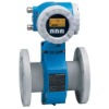
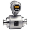
eh flowmeter
Application
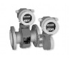
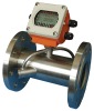
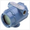
Endress+HauserElectromagnetic flowmeter for bidirectional
measurement of liquids with a minimum
conductivity of ≥ 50 μS/cm:
Acid, alkalis PaintsPastes Water, wastewater etc.
Flow measurement up to 9600 m³/h (42268 gal/min)
Fluid temperature up to +130 °C (266 °F)
Process pressures up to 40 bar (580 psi)
Lengths in accordance with DVGW/ISO
Application-specific lining material:
PTFE
Promag measuring devices offer you cost-effective flow
measurement with a high degree of accuracy for a wide
range of process conditions.
The uniform Proline transmitter concept comprises:
• High degree of reliability and measuring stability
• Uniform operating concept
The tried-and-tested Promag sensors offer:
•No pressure loss
Not sensitive to vibrations Simple installation and commissioning
Measuring principle Following Faraday's law of magnetic induction, a voltage is induced in a conductor moving through a magnetic
field.
In the electromagnetic measuring principle, the flowing medium is the moving conductor.
The voltage induced is proportional to the flow velocity and is supplied to the amplifier by means
of two measuring electrodes. The flow volume is calculated by means of the pipe cross-sectional area.
The DC magnetic field is created through a switched direct current of alternating polarity.Output signal Current
Ue = B · L · v
Q = A · v
Ue Induced voltage
B Magnetic induction (magnetic field)
L Electrode spacing
v Flow velocity
Q Volume flow
A Pipe cross-section
I Current strength
Electrical connection,
terminal assignment
Measured variable Flow velocity (proportional to induced voltage)
Measuring ranges Measuring ranges for liquids
Typically v = 0.01 to 10 m/s (0.03 to 33 ft/s) with the specified accuracy
Operable flow range Over 1000 : 1
Output
• Galvanically isolated
• Active: 4 to 20 mA, RL < 700 Ω (for HART: RL ≥ 250 Ω)
• Full scale value adjustable
• Temperature coefficient: typ. 2 μA/°C, resolution: 1.5 μA
Pulse/status output
• Galvanically isolated
• Passive: 30 V DC/250 mA
• Open collector
• Can be configured as:
– Pulse output: Pulse value and pulse polarity can be selected, max. pulse width adjustable (5 to 2000 ms),
pulse frequency max. 100 Hz
– Status output: for example, can be configured for error messages, empty pipe detection, flow recognition,
limit value
Signal on alarm • Current output → Failsafe mode can be selected
• Pulse output → Failsafe mode can be selected
• Status output → "Not conductive" in the event of fault or power supply failure
Load See "output signal"
Low flow cutoff Switch-on points for low flow are selectable.
Galvanic isolation All circuits for inputs, outputs and power supply are galvanically isolated from each other
Electrical connection,measuring unit
Connecting the transmitter (aluminum field housing), cable cross-section max. 2.5 mm2 (14 AWG)
a Electronics compartment cover
b Power supply cable
c Ground terminal for power supply cable
d Terminal connector for power supply cable
e Signal cable
f Ground terminal for signal cable
g Terminal connector for signal cable
h Service connector for connecting service interface FXA 193 (Fieldcheck, FieldCare)
i Ground terminal for potential equalization
Electrical connection, terminal assignment
Electrical connection, remote version
Connecting the remote version
a Wall-mount housing connection compartment
b Sensor connection housing cover
c Signal cable
d Coil current cable
n.c. Not connected, insulated cable shields
Terminal numbers and cable colors:
5/6 = brown, 7/8 = white, 4 = green, 37/36 = yellow
Supply voltage (power supply) • 85 to 250 V AC, 45 to 65 Hz
• 20 to 28 V AC, 45 to 65 Hz
• 11 to 40 V DC
Cable entry Power supply and signal cables (inputs/ outputs):
• Cable entry M20 × 1.5 (8 to 12 mm / 0.31 to 0.47")
• Thread for cable entries, ½" NPT, G ½"
Connecting cable for remote version:
• Cable entry M20 × 1.5 (8 to 12 mm / 0.31 to 0.47")
• Thread for cable entries, ½" NPT, G ½"
Remote version cable
specifications
Coil cable
• 2 × 0.75 mm2 (18 AWG) PVC cable with common, braided copper shield (∅ ∼ 7 mm / 0.28")
• Conductor resistance: ≤ 37 Ω/km (≤ 0.011 Ω/ft)
• Capacitance core/core, shield grounded: ≤ 120 pF/m (≤ 37 pF/ft)
• Operating temperature: –20 to +80 °C (–68 to +176 °F)
• Cable cross-section: max. 2.5 mm2 (14 AWG)
• Test voltage for cable insulation: ≤ 1433 AC r.m.s. 50/60 Hz or ≥ 2026 V DC
Signal cable
• 3 × 0.38 mm2 (20 AWG) PVC cable with common, braided copper shield (∅ ∼ 7 mm / 0.28") and individual
shielded cores
• With empty pipe detection (EPD): 4 × 0.38 mm2 (20 AWG) PVC cable with common,
braided copper shield (∅ ∼ 7 mm / 0.28") and individual shielded cores
• Conductor resistance: ≤ 50 Ω/km (≤ 0.015 Ω/ft)
• Capacitance core/shield: ≤ 420 pF/m (≤ 128 pF/ft)
• Operating temperature: –20 to +80 °C (–68 to +176 °F)
• Cable cross-section: max. 2.5 mm2 (14 AWG)
a Signal cableb Coil current cable1Core 2 Core insulation 3 Core shield 4 Core jacket 5 Core reinforcement 6 Cable shield 7 Outer jacket
Performance characteristics
Reference operating
conditions
As per DIN EN 29104 and VDI/VDE 2641:
• Fluid temperature: +28 °C ± 2 K (+82 °F ± 2 K)
• Ambient temperature: +22 °C ±2 K (+72 °F ± 2 K)
• Warm-up period: 30 minutes
Installation conditions:
• Inlet run > 10 × DN
• Outlet run > 5 × DN
• Sensor and transmitter grounded.
• The sensor is centered in the pipe.
Maximum measured error • Current output: also typically ± 5 μA
• Pulse output: ±0.5% o.r. ± 2 mm/s (±0.5% o.r. ± 0.08 in/s) (o.r. = of reading)
Fluctuations in the supply voltage do not have any effect within the specified range.
Max. measured error in % of reading
Repeatability Max. ±0.2% o.r. ± 2 mm/s (±0.2% o.r. ± 0.08 in/s) (o.r. = of reading)