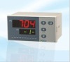
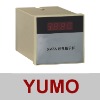
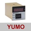
AI-704M High Performance Intelligent 4 Channel PID controllerMain Features:
- Programmable and modular inputs. Multiple input types of thermocouples and RTDs, voltage/current inputs and two-wire transmitters are field- selectable.
- Each channel can have independent input specification. All channels are equipped with digital adjustment and filtering functions and each channel have individual digital adjustment and filtering parameters.
- Provide high accuracy compensation function such as ice-point compensation, copper resistance compensation and thermostat compensation to thermocouple inputs.
- Build-in accurate internal calculation functions including square root extraction, summation, subtraction and multiplication.
- Support up to 2 isolated retransmission output. Any input channel can be retransmitted to OUTP port or all channels are cyclically retransmitted.
- Provide manual/auto pilot display, with 2 pilot speed selectable.
- Support up to 7 on-off signal inputs/outputs which can work as alarm output or on-off signal I/O for host computer.
- Each input channel has independent low/high limit alarm which can be assigned to any alarm output.
- Advanced communication function. Provide high accuracy and stability multi-channel analog data sampling function to host computer. The host computer can also input up to 7 channel on-off signal or execute on-off operation via the indicator.
- Up to 12 customized field parameters.
Model Code Legend
Designed with modular principle, AI-704M can be equipped with 6 modules on 6 sockets: M1, M2(MIO), M3(OUTP), ALM, AUX, and COMM. M1, M2 and M3 can be equipped with various input modules, each of which has 1or 2 analog input channels. ALM, AUX and M3(OUTP) can be equipped with relay output module, each of which has 1 or 2 alarm output channels. If necessary, M2 can also be installed with a single relay output module and work as alarm output. COMM can only be equipped with RS485 interface for communication with computer. M2 and M3 can be equipped with either analog input module for measurement or relay output modules for alarm. All inputs and outputs are programmable.
The ordering code of 704M is made up of 9 parts, for example:
| AI-704M | B | J1 | J2 | X3 | L1 | N | S4 | 24VDC |
| (1) | (2) | (3) | (4) | (5) | (6) | (7) | (8) | (9) |
(1) Shows the model of the indicator AI-704M respectively indicate 4 channels indicator.
(2) Dimension
(3)~(8) Symbols the module type installed on sockets ( M1,M2,M3,AL1,AL2,COMM):
| Module | Module Descriptions | M1 | M2/ MIO | M3/ OUTP | AUX | ALM | AUX | COMM |
| N | no module installed | √ | √ | √ | | √ | √ | √ |
| J0 | 1 channel three-wire RTD, thermocouple or mV voltage input | √ | √ | √ | | | | |
| J1 | 2 channel two-wire thermocouple or mV voltage inputs | √ | √ | √ | | | | |
| J2 | 2 channel two-wire RTD inputs | √ | √ | √ | | | | |
| J3 | 2 channel voltage inputs of 0-1V,0-3V,0-5V or 1-5V | √ | √ | √ | | | | |
| J4 | 2 channel current inputs of 0-12mA, 4-20mA, 0-20mA etc. | √ | √ | √ | | | | |
| J5 | 2 channel two-wire transmitter provided 24VDC power supply. | √ | √ | √ | | | | |
| L1 | 1 relay contact output (Capacity: 2A/250VAC, normal open terminal can absorb spark) | | | √ | | √ | √ | |
| L2 | 1 relay contact (NO+NC) output. (small volume, 30VDC/1A, 250VAC/1A) | | | √ | | √ | √ | |
| L5 | 2 relay contact(ON) outputs.(30VDC/1A,264C/1A) | | | √ | | √ | √ | |
| G | SSR voltage outputs (12VDC/30mA) | | | √ | | | | |
| X3 | 0~20/4~20mA linear current output module. (Use internal 12VDV power of the instrument) | | | √ | | | | √ |
| X5 | 0~20/4~20mA linear current output module. (With its own isolated power) | | | √ | | | | √ |
| S | Photoelectric isolated RS485 communication module (use instrument’s internal 12V isolated power) | | | | | | | √ |
| S4 | Photoelectric isolated RS485 communication module with its own photoelectric isolated power | | | | | | | √ |
(9) Shows power supply: Null indicates 100~240VAC power supply, and “24VDC” indicates 20~32VDC/AC power.