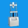
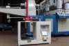
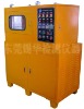
AEV Electric Test Stand Technical Parameter
| Model Number | SN-AEV-5KN | SN-AEV-10KN | SN-AEV-20KN | SN-AEV-30KN |
| MAX Load | 5000N | 10000N | 20000N | 30000N |
| Effective Stroke | 220mm | 1000mm | 1000mm | 1000mm |
| Testing Speed | 0-240mm/min |
| Dimension | 400*250*1050mm | 640*400*2400mm |
| Gross Weight | 75KGS | 90KGS |
AEV Electric Test Stand Features
- Electric loading, stepless speed regulation and gear drive
- Compact structure and stable drive
- Simple operation, can be used with a variety of fixtures
AEV Electric Test Stand Applications
AEV Electric Test Stand is used in push pull load and other destructive tests in the industries of rubber, plastics, light textile, building doors and windows, composite materials, wire and cable, auto parts, power machinery and research institutions, etc.
AEV Electric Test Stand Installation
Built-in Sensor
The 4-M6 screw passes through fixed block 4-φ6.2 hole, nested with one washer along the direction of screw thread and screwed tight with the 4-M6 thread on the dynamometer mounting plate 1. There are two groups of dynamometer mounting holes, respectively 30x145, 40x90. Users can determine them according to their own demands.
External Sensor
External Sensor: Remove the dynamometer mounting plate 1, allow the 2-M8 screw to pass through the fixed block 2-φ8.5 holes, to allow the external sensor connecting block to connect firmly with the fixed block, pass the M12 rut through connecting rod through-hole and connect firmly with the sensor. The control system can be installed on the dynamometer mounting plate 2.
Adjustment of Height
There is one locking bolt on both sides of fixed blocks of the AEV test stand respectively. Firstly, loosen the locking bolts, then move the fixed block up and down to the required height, and then lock the locking bolt tightly.
Adjustment of Stroke
There are two stroke limit screw on the guide pillar (note: removal of limit screw is prohibited). The limit sheath is permitted to travel only within the travel range. Regulate the position of limit sheath according to user’s measurement requirements to achieve the intended purposes.
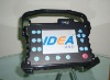
Control Panel
1. Power switch: Press the button and the power is switched on; then presses again, the power is switched off.
2. Speed Controller: Control the movement speeds of the movable block within the range of 0 ~ 240mm/min. users may choose appropriate moving speed according to their requirements.
3. UP Key: move the working platform upward.
4. STOP Key: Stop the movement of the working platform.
5. DOWN key: Move the working platform downwards.
6. Manual / Auto switch key:
A. when the key is switched to the Manual, press and hold the (UP) key or press and
hold the (DOWN) key, to move the working platform; and release the(UP)key or
(DOWN)key, to stop movement of the working platform.
B. when the key is switched to the Auto, press the (UP) key or press the (DOWN) key directly to move the working platform back and forth; and press the STOP key to stop the movement.
7. How to use the counter: There are two lines of the digital displays on the counter, the upper part is to record the test frequency (i.e. frequency of real-time measurement), and the lower part is the pre-set buttons, 4 in total, respectively one, ten, hundred, thousand from left to right, representing that the pre-set value should be within the range of 0 ~ 9999 (pre-setting is arbitrary), for instance, if a user need to carry out continuous test on a certain product with the test time of 9999, it is required to regulate on the four buttons to display 9999, and then press the Manual/Auto buttons to carry out 9999 times of tests. After running for 9999 times automatically stop; if re-testing is required, press the Stop button.